








WT Magnetica
Precision, connectivity, and simplicity for chemical dosing in water treatment systems
WT Magnetica: configuration and view of the pump assembly.
EMEC’s new WT Magnetica brings to water treatment management a membrane dosing solution driven by an electromagnetic solenoid, designed for applications where control, reliability, and digital integration must coexist within a single system. The design combines proven pulse dosing technology with an advanced electronic interface and connectivity features geared toward modern plant management.
MEMBRANE DOSING • UP TO 3 L/h • UP TO 45 pulses/min
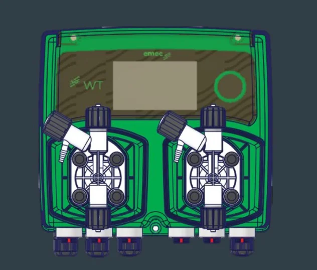
A New Generation of Magnetic Dosing
At the heart of the WT Magnetica is a membrane technology for pulsed dosing, driven by an electromagnetic solenoid and controlled at up to 45 pulses per minute. The product documentation specifies a dosing capacity of 0 to 3 L/h with a K-series pump body and operation up to 2 bar: a combination designed to provide precise and consistent control under the intended operating conditions.
Advanced control, directly on the machine
The WT Magnetica features a 3-inch backlit LCD display (128×64) with an encoder and an advanced navigation menu. This provides the operator with a clear interface for managing the pump, while the platform offers 8 operating modes. These include weekly and daily programs, pulse-based control linked to the water meter, and functions dedicated to managing the dosing of biocides and inhibitors.
Connectivity for an Increasingly Digital Management
Approach WT Magnetica is designed from the outset for a connected approach. Modbus RS485 communication, along with Wi-Fi and Bluetooth Low Energy options, allows it to be integrated into more advanced control architectures. It also features remote control and firmware update capabilities via a web service or app, paving the way for more flexible management, predictive maintenance, and integration with Industry 4.0/5.0 systems.
Designed for water treatment
The WT Magnetica is specifically designed for chemical management in small cooling towers, where the management of biocides and inhibitors requires continuity and control. Its configuration and available interfaces make it suitable for integration into systems where the dosing system must communicate with water meters, flow sensors, level signals, and other monitoring devices.
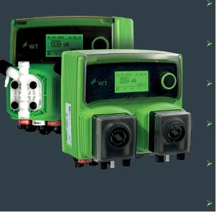
The WT family: The WT Magnetica stands out for its diaphragm pumping system.
Electrical I/O Interfaces: WT Magnetica Communicates with the System
WT Magnetica provides an I/O interface architecture designed to connect the pump to the main signals and devices of a water treatment system. The connections are organized into clearly defined blocks, simplifying integration with the plant and control systems. On the left side are the power supply, the VAC power output for the bleed (up to 5 A), the dry-contact alarm output, the RS485 Modbus communication port, and the Standby input. On the right side are the water meter input, the Level 1 and Level 2 inputs, the optional conductivity probe input, and the flow sensor input.
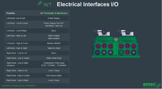
The WT Magnetica’s I/O interfaces: connection layout and configurations are illustrated in the product documentation.
The most interesting aspect is not just the number of available connections, but the way these interfaces allow the pump to become an active part of the system architecture. The WT Magnetica can receive information from the water meter and flow sensor, manage level signals, and communicate with external systems via Modbus RS485. In addition to these functions, there is a dry-contact alarm output and a standby input, which are useful for coordinating the pump’s operation with the installation’s safety and control logic.
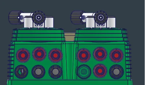
Graphical details of the connection configurations shown for the WT platform.
This configuration makes the WT Magnetica a particularly attractive solution for those seeking a dosing system that does not operate in isolation but can be integrated into a larger system. The interfaces are, in fact, designed to support process management: from reading signals from the plant to communication and supervision, with a structure that keeps the connection points accessible and clearly defined.
Industrial Design and Simplified Maintenance
The WT Magnetica design is based on modularity and accessibility: the connection points are clearly defined, and the components are arranged to simplify installation, service, and maintenance. The injection-molded PC/ABS housing gives the pump an industrial design consistent with the EMEC family, while its IP65 protection rating helps ensure it is suitable for its intended installation environment.
Technical Specifications and Interfaces: A Comprehensive Platform
| Feature | WT Magnetic |
| Technology | Membrane, pulse dosing with an electromagnetic solenoid |
| Dosing capacity | 0–3 L/h (K pump head) |
| Pressure | Up to 2 bar |
| Pulse Control | Up to 45 pulses/min |
| Operating Procedures | 8 |
| Interface | 3-inch backlit LCD display (128×64) + encoder |
| Communication | Modbus RS485 |
| Connectivity | Wi-Fi, Bluetooth LE |
| Digital Services | Remote control and firmware updates via web platform/app |
| Power Supply | 115 VAC / 230 VAC |
| Protection | IP65 (IEC 60529) |
| Dimensions | 213 × 210 × 130 mm (W × H × D) |
| Target Application | Cooling Tower |
The EMEC Value: Precision, Scalability, and the Future
WT Magnetica combines four distinctive features into a single platform: dosing precision, scalability, connectivity-ready technology, and simplified maintenance. The goal is to offer a solution that does more than simply dose the chemical—it can become an integral part of the water management system.
WT MAGNETICA — THE DOSING SYSTEM THAT INTEGRATES WITH YOUR SYSTEM.
EMEC • As Simple as Water
| Location | Interface | Function |
| Left block | Power Supply | Power Supply |
| Left block | Power Supply Output VAC | Power supply output for Bleed, max 5 A |
| Left block | Alarm Output | Alarm output, dry contact |
| Left block | Modbus RS485 | Serial communication |
| Left block | Standby Input | Standby Input |
| Right block | Water meter input | Water meter input |
| Right block | Level 1 Input | Level 1 Input |
| Right block | Conductivity Probe Input | Optional conductivity probe input |
| Right block | Flow sensor input | Flow sensor input |
| Right block | Level 2 Input | Level 2 Input |